Part Selection Guide
Passive Parts
C1 (film)
This position has a trace shorting its pins, since I recommend you leave this part out unless you know you want it. It’s easy to cut the trace to force the signal to go through the cap, such as with a Dremel tool or hobby knife.
To understand the issues involved in deciding whether to add C1 or leave it shorted, read my article Input Capacitors for Headphone Amps.
A 10 mm pin pitch box cap works best here. You should be able to find metalized polypropylenes in suitable values. Certainly metalized polyesters exist in values large enough.
Optional? Yes. A jumper is not necessary, as the pads are shorted on the board.
Largest Part Size: 12.5 mm × 8 mm
C2, C3 (electrolytic)
These are the main power reservoir capacitors, also called the “rail capacitors” because they span the power rails.
Use 100 µF to 1000 µF capacitors with voltage ratings higher than that of your power supply. For example, use a 25 V capacitor if your power supply is 24 V. It’s generally best to populate all four positions, though you can get away with populating just one + and one - cap position.
If you want to get your capacitors from one of the major distributors, look into the Panasonic FM, Panasonic FC, and Nichicon PW lines. The Panasonic FC and the Nichicon PW are identical, specwise. The Panasonic FMs are a little nicer than the FCs, but there are fewer values and fewer case size choices in that line. If your chosen distributor doesn’t carry one of these lines, try to find a cap line that features long life and low ESR.
If you want to choose your own power capacitors, there are two main rules to keep in mind:
- Bigger is better, within a particular line of capacitors.
- It’s usually better to use a lower-capacitance part from a better line of capacitors than a higher-capacitance part from a poorer-performing line of caps.
Sometimes you must compromise on quality (rule 2) to get a sufficient amount of capacitance (rule 1). For a PIMETA, the minimum I recommend is four 220 µF caps or two 470 µF caps. If you’re looking at caps over 1000 µF you’re probably compromising too much on quality; try looking for a line of capacitors that will let you trade some of that excess capacitance for higher quality. If you’re already looking at the best capacitor line available to you, you may simply choose not to buy that 2200 µF capacitor, but instead get the 1000 µF one and save some money. I doubt you can hear the difference.
Now to more specific advice.
First, decide on the capacitor’s dimensions. The diameter should be 12.5 mm or 10 mm, as these fit best on the PIMETA board. If it’s skinnier, the lead pitch will be too narrow for the cap to securely mount on the board. If it’s too fat you’ll only be able to use two of the positions, or you’ll have to mount the capacitors off the board. The height will be limited by the amount of space above your board inside your case. You don’t have to use the tallest cap that will fit, you just need to keep this in mind as a limit.
Next, you need to know your power supply voltage. It’s best to use caps with a voltage rating that’s higher than your power supply’s maximum output voltage, but no higher. For instance, if you have a 30 V supply, 25 V caps could be damaged by the power supply, 35 V caps are good, and 50 V caps are wasteful. (For more on this topic, read my article Op-Amp Working Voltage Considerations.)
You may notice that the caps only have half the full power supply voltage across them in normal use. 16 V caps would work in the above example. However, this assumes that the virtual ground is always precisely centered between the rails. That is indeed what happens in normal operation, but it’s wise to design for abnormal conditions as well. There are several ways to collapse the virtual ground. You don’t want to have to replace all your rail caps if there is ever a virtual ground fault, do you?
Optional? You must populate at least one “+” cap and one “-” cap. Leave the remaining positions open if you don’t populate all four.
Largest Part Size: 12.5 mm diameter
C4 (film)
These are the high-speed reservoir caps: they provide current briefly while the big and slow electrolytics get around to discharging. They are optional, but adding them can improve the dynamic behavior of the amp. Try to find the largest film type capacitor you can that will fit; the hole spacing allows 0.2 in (5 mm) pin spacing, which is a common size for polyester box caps. You should use at least 1.0 µF here, and if you do some hunting you can find caps up to 10 µF that will fit here. You can probably find suitable caps up to about 3.3 µF without too much work. Beyond that, the hunting gets hard.
In my humble opinion, the ideal capacitor for C4 is the Wima MKS 2 series of box caps. Most film capacitors are long and thin, but the Wima MKS 2 series has a squarish footprint which is a perfect match for the boxy section of the PCB given to C4. Another bonus is that larger capacitance parts in this series tend to be taller rather than wider, so they take up very little board space. All of the PCM 5 parts in this series will fit in the C4 position, up to and including the 6.8 µF/50 V and 10 µF/16 V parts. (These two are the same physical size.)
Optional? Yes, do not jumper.
Largest Part Size: 10 mm × 12 mm
C6G (NP0 ceramic)
This is necessary for the stability of the ground channel. It may be possible to get away without it, but I’ve seen too many misbehaving amps cured by adding this cap to try going without it.
Optional? No.
Largest Part Size: 0.1 in (2.5 mm) pin pitch
R1
The main purpose of R1 is to help balance the op-amp’s input impedances. Use the value on the schematic unless you have a good reason not to. If you do change it, it needs to be the same in all three channels, and it should be equal to R3 + R5. It is not essential that this relationship be maintained, but it will help balance the amp’s sound.
In the left and right channels, R1 interacts with R2 to form a voltage divider. If R1 is much smaller than R2, this effect is negligible, which is the way you’ll almost certainly want it. In rare situations, one might choose to configure this to divide the voltage down by a significant amount on purpose.
Optional? Technically yes, in which case you’d jumper it, but I recommend you always populate it.
R2 (left and right channels only)
This is the input impedance resistor. It should be around 10× the value of your volume control.
Higher is better than lower because the lower the value, the more your source will see the amp as a varying impedance load as you rotate the volume knob. This may cause it to have different sound characteristics at different volume levels. You don’t want to go too high, though, because the larger the value, the more electrical noise gets added to the circuit. Any noise added here, at the input stage, gets multiplied by the amp’s gain. Consider the schematic value of 1 MΩ a maximum. This allows for up to a 100 kΩ pot, also the highest value you should use.
Optional? No.
R3 through R6 (left and right channels only)
These are the feedback resistors. They set the amplifier topology and the gain. Although there are a couple of different reasonable topologies possible, I only recommend Jung multiloop unless you’re just playing around. This requires populating all four positions per channel.
The simplest path is to just use the values given on the schematic. Next simplest is to leave R3, R5 and R6 at their default values and adjust R4 to change gain. (Gain calculator.) If you want to fiddle with everything, read about how to optimize the multiloop values.
Optional? For a standard configuration, populate all four positions.
R3G
This is normally left open. (Thus “inf.” in the schematic: infinite resistance.) It is there in case you want to try a chip with bipolar input transistors in the ground channel. If you’ve used bipolar-input chips before, you know why you want R3. If not, stick to FET-input chips.
Optional? Normally left open.
R4G
This should be equal to R1 unless you use R3G.
Optional? No.
R7
We reserved this part number in the PIMETA for those familiar with the META42 or PPA. In the PIMETA, there is no series resistor between the op-amp and the buffer since the BUF634 has 200 ohms of series resistance on its input already. Hence, there is no need for an “R7”.
R8
If you are getting audible hiss at normal listening volumes with the source disconnected, put a 10 to 100 Ω resistor in R8. Alternatively, you could put the same amount inline with the line from the output pad to the jack. (This would be like R9 in the META42.) The difference is between output resistance inside the feedback loop or outside it, which have different effects but both can fix the problem. The side effects are different, so investigate it if you want to try this.
Optional? Yes. Jumper it.
R10
If you bias the op-amp into class A with JFET cascodes, you should also add R10. JFETs have an input capacitance, and you don’t want a capacitor across the output of the op-amp. R10 is a kind of “insulation” between the two, so they don’t affect each other as much.
The exact value of this resistor is not critical, but it does have to fall within a certain range. If it’s too low, it doesn’t do its job very well; 100 Ω is probably the smallest value that will provide appreciable benefit. If it’s too high, it will cause the cascode to fall out of regulation during parts of the swing of the op-amp’s output, negating its advantages; 1 kΩ is about the largest you can get away with.
Optional? Yes. Populate it if you bias the op-amp into class A. Leave it empty otherwise.
R11
This resistor is for modifying the bandwidth of the buffer (BUF634 only), which can improve its sound audibly.
The highest useful value for this resistor is about 4.7 kΩ. As the value drops, the buffer’s bandwidth and quiescent current draw go up. (The graph “Quiescent Current vs Bandwidth Control Resistance” in the datasheet shows the relationship.) According to tests by KurtW and others, distortion drops as bandwidth goes up, though once R11 falls below about 200 Ω, distortion starts rising again.
If you’re stacking your buffers, R11’s value needs to be halved every time you double the number of buffers in order to maintain the same bandwidth setting. This means that the minimum R11 value should be 100 Ω with two stacked buffers, not 200 Ω.
Optional? Yes.
RLED
This is the LED current limiting resistor. Use Ohm’s law to figure current given the LED’s voltage drop and the power supply voltage. For example, consider a 1.8 V LED with a 15 V power supply and a 4.7 kΩ RLED:
      I = V/R
      I = (15 - 1.8) / 4700
      I = 0.0028
So, 2.8 mA goes through the LED.
Most LEDs require 1 mA to get minimum useful brightness. More current gets you more brightness, but of course uses more power, which mainly matters with battery power supplies. Most LEDs are rated for at least 20 mA, but that’s annoyingly bright for a power indicator.
Typical values are 1 kΩ to 10 kΩ. I personally use 2.2 kΩ and 4.7 kΩ most often.
Notice that RLED is just a pad on the board. The other leg goes in the RFET hole farthest from the RLED pad.
Optional? Yes. Jumper only if your LED has an integral resistor. Most don’t.
FET
This is a JFET set up as a constant current source for the power LED. This keeps the LED at a constant brightness in battery-powered amps, since a battery’s voltage drops as it is used up.
Optional? Yes. Use in conjunction with RFET, or use RLED in place of both FET and RFET. Do not jumper.
RFET
This is a source resistor for tuning the current through FET. As you raise the value of RFET, the current through this pair drops. A useful range is 10 Ω to 1 kΩ. For small JFETs (1-5 mA) you want to stick to the lower end of that range. It’s not essential to use RFET with FET; you could put a jumper here and just live with whatever IDSS value you get from your JFET.
The FET and RFET combination will be used most often in conjunction with ZNR.
Optional? Yes.
ZNR
This is a zener diode inline with the LED. Its purpose is to turn off the LED when the power supply voltage drops below some critical value. It’s intended for giving you a hint that your battery needs to be changed or recharged. You use it in conjunction with FET and RFET, which keep the LED at a constant brightness until the zener shuts the LED off.
To set the zener voltage, you need two things: the LED’s forward voltage drop and the minimum working voltage for your setup. The LED voltage will be in its datasheet. The minimum working voltage is tricky to figure out; you do it one of two ways depending on your setup.
It’s easiest to figure this out if the battery runs down before the amp starts clipping. This can happen because each cell in a battery will still have about 0.9 V when the cell is useless. With rechargeables, the cell voltage is dropping quickly by the time you get to 0.9 V. With alkalines, the voltage is still dropping slow and steady at this point, but the internal impedance of the cells will have risen high enough that the amp will start sounding bad. Simply multiply the number of cells by 0.9 V and compare that to your op-amp’s minimum working voltage with your headphones. If the battery’s minimum voltage is higher than any combination of headphones and op-amps you will use, your amp’s minimum voltage is equal to the battery’s minimum voltage. (9 V alkalines have 6 cells. 9 V rechargeables have between 6 and 8; check the datasheet.)
If you go through the procedure and find that your amp will start clipping before the battery is dead, things get a bit trickier. If you will use only one set of headphones with the amp, that combo’s minimum working voltage is your amp’s minimum working voltage. If you will be using more than one different headphones with the amp, you will have more than one minimum working voltage to choose from. Which do you use? Instead of trying to come up with a satisfactory answer to that question, I think you’re better off either raising your battery pack’s voltage, changing to a more voltage-efficient op-amp, or just not using this feature.
The LED’s voltage drop plus the zener’s reverse breakdown voltage is the cutoff voltage. If this is very close to your amp’s minimum working voltage, the LED will shut off right about when you need to change or recharge the amp’s battery. The tricky bit here is that this circuit doesn’t have a perfectly sharp cutoff point. About a volt above the cutoff voltage, the LED starts to dim, and in the last several tenths of a volt above full cutoff, the LED dims rapidly. You probably want the LED to go completely dark before the battery needs to be changed or recharged, so setting the zener voltage equal to the amp’s minimum voltage minus the LED’s voltage drop is a good starting point. You might buy two additional zeners, one the next step higher and the other the next step lower for tuning this if it doesn’t work the way you expect.
When picking parts for this circuit, you want to use zeners rated down in the hundreds of milliwatts, usually in DO-35 packages. The big power zeners have leads that are too thick to fit in the holes.
If you want to use FET and RFET without the cut-off zener, you can just jumper the zener position. This will give you constant LED brightness as the battery voltage drops. If you aren’t making a battery-powered amp, FET and RFET have no functional advantage over RLED.
Optional? Yes. See text for jumpering details.
D1
This is an optional “crowbar” diode. If you put a diode here, it will normally be unused, since it’s reverse-biased with respect to proper power supply connection. But if the power supply is connected backwards, this diode will short-circuit the power supply so that your amp circuit’s components aren’t damaged. If the power supply is a battery, it will make the battery overheat and possibly leak, but that’s preferrable to frying your op-amps and buffers.
The type of diode to use here isn’t terribly critical, but in general, standard silicon types tend to be rated for high voltage and relatively low amperage. A better sort for this application is a Schottky diode — these are typically only good for 20-40 V, but higher amperage than standard diodes. Perfect. The board is designed to accept diodes in DO-41, DO-201 and TO-220 packages. Readily-available Schottkys that will work here are the 1N5817-5819 (20-40 V, 1 A), the 1N5820-5822 (20-40 V, 3 A) and the 10TQxxx (30-45 V, 10 A). If you only need a 1-amp crowbar, the standard-type 1N400x diodes may be a better alternative since they’re cheap and as common as dirt — even Radio Shack has them.
Those aren’t the only options. Other examples are the 3 A 1N540x series diodes, and the 5 A HER50x series. Radio Shack carries all of these, or you can get them at Mouser or other places.
If you’re using AC power, a better alternative is to put a diode inline with one of the wires to the board. This will have a small voltage drop, but it will cut the power supply off completely in the event of a reversed supply, rather than short circuiting it. Thus, you can get away with a much smaller diode. This method is also good with battery powered amps when there’s at least 0.7 V between the battery pack’s minimum voltage and the minimum voltage your amp needs to power your headphones. This will happen when your battery pack’s minimum voltage is relatively high.
If you do go with the crowbar method, beware that shorted alkaline cells can put out 4-5 A initially and may take about a minute to ramp down to below 1 ampere. Rechargeables can put out several amperes continuously. Therefore, a 1 A diode is likely to burn up when used this way. You want to use a 3 A diode at minimum, and going with a 5 A or 10 A diode will give even more safety margin.
Another thing you have to pay attention to is that some Schottkys have a lower reverse voltage spec than their forward voltage spec. It’s reverse voltage you care most about, since that’s how the diode will be used virtually all the time. For example, the 1N5817 has a 20 V forward voltage tolerance, but only a 14 V reverse voltage tolerance. If you were using a pair of 9 V batteries in series, this diode would likely fail in normal operation, since it’s reverse biased except when the batteries are plugged in backwards. You’d need to step up to the 1N5818, which has a 21 V reverse voltage tolerance.
If you use the crowbar, you might consider also adding a fuse to the amplifier. If you add, say, a 500 mA fuse, it will only blow if the current in the amp gets extraordinarily high, which should only happen when the amp has been crowbarred. (If you have buffer stacked high on your amp outputs, a high load or an output short could also blow the fuse, but that’s probably a good thing for a headphone amp.)
Optional? Yes, do not jumper.
Are 1/8 W Resistors Sufficient?
1/4 W resistors are the most readily available sort and the board will accept standard 1/4 W resistors, but it takes extraordinary circumstances to make the circuit put more than 1/8 W through one of the resistors.
Under abnormal loads, you could conceivably put more than 1/8 W through R8. It comes down to a question of how much current your href="#buffer">buffer
configuration can put out and what the output load is. With a stack of 4 BUF634s on each channel and a dead short across the output, you can definitely burn up an R8, if the power supply doesn’t quit first. Even under lighter conditions, like trying to power speakers, you could cook an 1/8 W R8. This is all fairly unlikely, but it’s something to consider.Resistor Sizes
The resistor pads on the PIMETA board are only 300 mils apart, which limits the size of the resistors you can use. Standard 1/4 W metal film and carbon resistors will fit in the board without a problem. If you use Vishay Dale CMF series resistors, use the RN55 series, not the RN60s. These are 1/8 W, but as I explained above, 1/8 W is sufficient. RN60s will not fit in the board without creative mounting.
Single Voltage or Dual Voltage Power Supply?
The PIMETA board is designed for single-voltage power supplies. These have just a positive and a negative terminal. These are connected with wire to the + and - pads on the board. There’s a “rail splitter” on the board (the TLE2426) which splits this single voltage into a virtual dual voltage. For instance, a single 24 V supply effectively becomes +/-12 V.
If you leave the TLE2426 out, you can instead use a genuine dual voltage power supply. A dual supply has 3 terminals: +, - and ground. You run + and - to the board just as you would for a single-voltage supply, and you run ground to the TLE2426 OUT pad; that’s the one closest to the “TLE” silkscreened on the board.
I’ll assume you’re using a single-voltage supply from here on, since that’s the standard configuration. If you want to use a dual supply, you’re on your own.
Choosing a Power Supply
A power supply voltage somewhere in the 9 to 24 V range will serve you best. More voltage will probably hurt more than it helps, and lower voltage will require very careful part choices to make a workable amp. For a complete discussion on how to measure and calculate your way to the ideal power supply voltage level for your situation, see my article Op-Amp Working Voltage Considerations.
If you’re going to use batteries, it’s simplest to put them all in series. This gives you a single supply. It’s possible to make a dual supply with batteries, but there are dangers in this; do a search in the Head-Fi DIY forum archives, it’s been discussed before. A third option is to put two or more batteries in parallel, for increased battery life.
If you’re going to use a wall power supply (a.k.a. “wall wart”, “AC/DC transformer”), you also need to take care of the type of power supply you use. The two words you need to look for are regulation and isolation.
An unregulated power supply’s output voltage will fluctuate as the wall voltage fluctuates. Also, unregulated power supplies tend to be cheap all around, so they’ll have a lot of ripple and noise on their outputs. The PIMETA design doesn’t do much to eliminate noise and ripple (N+R) on the power rails; the power caps and the op-amps and buffers will reject some of the N+R, but they won’t get rid of all of it. (See my Op-Amp Power Supply Quality Considerations article for more info.) If there’s enough N+R on the rails, it can get into the amp’s output in audible levels.
A regulated power supply’s output will not fluctuate as the wall power fluctuates, and they generally have much better N+R behavior than cheap unregulated wall warts. Most power supplies that are simply called "regulated" are in fact switching power supplies. These can have more noise than unregulated supplies, because of the way they work. The better type of regulation for audio is linear regulation. If it doesn’t say “linear regulated”, assume it’s a switcher.
Your power supply also needs to be isolated, which means that the output leads are not directly connected to any of the input leads. It’s common in commercial power supplies to tie the DC output V- pin to earth ground connection on the AC side; this has safety and noise advantages, but makes it non-isolated. Tying V- to earth ground in a PIMETA can cause problems, since this places the virtual ground several volts above earth ground. If you plug the amp into a source component that uses earth ground for its outputs, the amp’s virtual ground will sit there fighting against the source’s true earth ground. The amp probably won’t win that fight.
If you use an isolated supply, the amp’s virtual ground can "float" to whatever level is required by the source, and V+ and V- will float right along with the virtual ground. Any supply with a transformer directly between the AC side and the DC output (i.e. most linears and unregulated supplies) is isolated. There are ways to make a switching power supply isolated, but check to be sure: most switchers are not isolated, in my experience. Because it’s uncommon, if you have a switching power supply that doesn’t say that it’s isolated, assume that it isn’t.
Bottom line: use linear power supplies or batteries to keep your life simple.
it is quite possible to diy an entire linear power supply, rather than buy one off thes shelf. i no longer offer linear power supply circuit boards, but you may be able to build something yourself along the lines of my old tread or yjps designs. there are many possible variations on those two designs, plus many other linear power supply designs available.
Choosing Your Op-Amps
There are three op-amps in the PIMETA circuit: one each in the left, right and ground channels.
The left and right channels are served by a dual-channel chip, OPALR. If you want to use single-channel chips, BrownDog offers adapters that take two DIP-8 or two SO-8 op-amp chips and adapts them to work in the DIP-8 pinout of OPALR.
The ground channel is served by a single-channel op-amp, OPAG. You can use the single-channel version of the op-amp you used in OPALR, but this is not required. See below for comments on using a different type of chip in OPAG than in OPALR.
Wherever the PIMETA board accepts a DIP-8 chip, it also accepts an SO-8. The SO-8 pads are nested within the DIP-8 footprints, on the bottom side of the board. In most cases, I recommend using the DIP-8 footprint, because it’s easier to solder and lets you use sockets.
Sockets let you swap chips easily for repair and op-amp rolling. If you want to use an op-amp that’s only available in SO-8 form, you can still use sockets by first adapting the op-amp to DIP-8; Brown Dog has an adapter for that, too. For DIP-8 chips, sockets have an additional benefit: they remove the possibility of overheating the chip with your soldering iron, since the socket takes the heat.
Sockets and adapters can cause problems. They add lots of little tiny “parasitic” resistances, capacitances and inductances to the circuitry around the op-amp. The slower the chip, the less likely these parasitics will matter. Generally speaking, it’s best to solder the op-amps directly to the board when they’re around 100 MHz or faster. This speed restriction doesn’t apply to any of the buffers recommended here for this board, as they’re all open-loop types; the parasitics of the whole circuit board are the main concern there. If you’re using an op-amp as a buffer or are using something else with a closed feedback loop, these local parasitics do matter, so you’d want to treat them the same as you would the other op-amps in the circuit.
Most any op-amp can be made to work in the PIMETA board, but some are more suitable than others. It’s best to use FET-input op-amps, rather than bipolar-input op-amps. You risk high DC offset at the output of the amplifier with a bipolar-input chip unless you do some very careful design. Also, really fast chips (roughly, 100 MHz and up) may require special attention; see the above commentary on sockets and adapters for one aspect of this.
OPALR does all the voltage amplification in the PIMETA circuit. The chip(s) you use here have the single biggest effect on the amp’s sonic signature, so it behooves you to pick this part carefully.
OPAG also affects the amp’s sonic signature, but not as much as OPALR. Some argue that you should use the single-channel version of the chip you used for OPALR in OPAG; the theory goes that because the ground channel must counteract the currents created by the left and right channels, using the same type of chip in all three channels is likely to give the lowest distortion since they all react to the signal in the same way. In practice, people have reported sonically interesting results from putting different types of chips in OPALR and OPAG. Sometimes one is forced to use different types of chips, either because your OPALR chip of choice doesn’t come in a single-channel version for OPAG, or because the op-amp type you’re using in OPALR isn’t unity-gain compensated (e.g. OPA637, OPA228) and so won’t work in the ground channel.
The canonical parts for this amp are the Analog Devices AD8620 for OPALR and the AD8610 for OPAG. They are reasonably priced, sound good, are readily available, have low current draw, and work down to lower supply voltages than many other good audio op-amps. While I wouldn’t call this chip “aggressive,” it is quite detailed, especially at the high end. This may mate well with your system and music or it may reveal problems you’d rather hide.
Mellower chips that also work well in this amp are the AD843, AD8066/8065 and OPA637/627. For reviews and more recommendations, see the companion article, Notes on Audio Op-Amps.
Choosing Your Buffers
The PIMETA board was designed to use the Burr-Brown (now TI) BUF634. TI seems to make them in batches, and when they’re between batches, these buffers can be difficult to find.
Unlike with op-amps, there is no universal pinout standard for buffers. As far as I know, there is no pin-for-pin drop-in replacement for the BUF634. This is not to say that there are no alternatives. Some of these alternatives are sufficiently close to pin compatibility that the modifications to make it work in a PIMETA are quite minor. I will discuss these alternatives in order of increasing difficulty of adaptation.
Of these alternatives, I have only heard the first in a PIMETA. Some of the other chips I’ve heard in different amplifiers, but I can’t personally recommend them in a PIMETA since I’ve not tried that. I’ve collected as much info here as I can verify, but in the end, I only have solid experience with the BUF634 in the PIMETA, so take all this with a grain of salt.
-
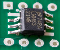
National Semiconductor’s LMH6321 (note the H...not to be confused with the LM6321!) is a near drop-in replacement for the BUF634. It is available in two packages; the PSOP-8 version fits on the SO-8 pads on the bottom side of the PIMETA board. You could try to adapt it to the DIP-8 footprint with a BrownDog adapter so you can socket it, but the chip is so fast this is likely to make the amp oscillate. The other trick with this buffer is that it uses pins 1 and 5 for different things than the BUF634. Since they’re not critical to the way the PIMETA works, you can just lift the pins so they don’t touch the board, or cut them off the buffer entirely. With pin 1, you have a third choice, which is to simply leave R11 out, or remove it from the board if you had one installed.
The final result looks like the picture at right.
This chip thumps. It might even be too bassy for your preference if you use it with a bass-strong chip like the AD8610/20 and bassy headphones.
Another thing to beware of with this chip is that it draws more current than a BUF634 even with the lowest recommended R11 value. A stack of two BUF634s with the lowest recommended R11 draws more than an LMH6321, but not by much, and you could choose to increase the R11 value and beat the LMH6321. If you were looking for an amp that lasts a long time on battery power, you should try to find some BUF634s or choose another low-current alternative from the choices below. On the other hand, my initial sense from playing around with these buffers is that they sound better for the current they draw, so you might well choose to give up some battery life to get the better sound.
-
The BUF634 pinout is nearly the same as for a single-channel op-amp. You can configure a unity gain stable op-amp as a buffer by connecting its OUT pin (pin 6, for DIP-8 and SO-8 singles) to its -IN pin (2). You need to use a high-current op-amp for this to be useful; else, might as well just leave the buffers out for all the good they’ll do. Because the buffer is inside the op-amp’s feedback loop in the PIMETA design, the buffer has to be faster than the op-amp in order to keep the amp stable. A particularly bad choice you will find recommended by some is the OPA551: high output current, yes, unity gain stable, yes, but slower than any of the op-amps recommended for OPALR and OPAG. If the buffer were outside the op-amp’s feedback loop, the OPA551-as-buffer would work well here, but it isn’t, so it won’t.
-
National Semiconductor recently began offering the LME49600, which looks very similar to the BUF634, on paper. It even has the bandwidth adjustment pin, so you can use R11. Those who have heard it say it does sound a little different from the BUF634, but this may just be a result of its higher minimum bandwidth and bias current; I don’t know that anyone has tried to control for that variable. Unfortunately, this part doesn’t (yet?) come in DIP-8 or SO-8 packages, so you will have to get creative to make it work. You’d have to bend the leads to fit wherever possible, and solder short (!) bits of hookup wire to its leads where necessary.
-
The Intersil HA-5033 and TI/Burr-Brown OPA633 have the same pinout; they may actually be the same design. Their pinout is similar to that of the HA-5002 (below), only without the dual supply option. These pinouts are all radically different from that of the BUF634. If you can find these buffers in the metal can package, that may be the easiest to adapt to the board, because the leads are relatively long and flexible. If you have to use the DIP-8 version, you may want to make adapter boards for it rather than futz with lead bending and hookup wires. Although later versions of the PPAv1 boards did allow use of these buffers, I don’t recall actually trying them in any of my amps. You may be able to find some old PPAv1 reviews with head-to-head reviews of the sonic differences. I can’t recall any, but they may be out there.
-
We used the Intersil HA-5002 in the PPAv1. I liked it well enough that I considered using it for the PIMETA, but its relatively high minimum supply current nixed that idea. I think the HA-5002 sounds better than the BUF634, even stacked and biased up. The HA-5002 has no output current limiting, so you have to be careful about plugging headphones into the amp while music is playing; most TRS jacks’ right channel contact momentariy gets shorted to ground as you insert the plug, which could cause a surge through the buffer big enough to destroy it. If you can live with the high current and lack of output current protection, it’s a fine alternative to the BUF634. The same commentary with regard to package type and adapters applies to this as to the HA-5033/OPA633. The main difference between these chips’ pinouts is that the 5002 has two pairs of power supply pins. The idea here is that you can get better performance by hooking V1+ and V1- to a nice, quiet, low-current supply and hooking V2+ and V2- to a separate high-current supply, which will necessarily have more load-modulated ripple. There is only one power supply in the PIMETA, so unless you want to get clever, just hook the buffer’s V1+ and V2+ to V+ in the PIMETA, and the buffer’s V1- and V2- to V- in the PIMETA.
-
Finally, there are several discrete buffer designs out there. Perhaps the easiest to apply, since you can get circuit boards for them, are Per-Anders’ QRV05 diamond buffers. If etching your own boards or using perfboard doesn’t bother you, Sijosae’s BUF634 drop-in is pretty easy, as these things go, though rather unsophisticated. Getting more complex, the Millet diamond buffer is reported to work well for applications like this. Similarly, daughter-boards for the diamond buffer design we have in the PPAv2 would work nicely with the PIMETA.
Choosing a Volume Control
There are three major varieties that work directly with the PIMETA amp board:
ALPS RK097/8: This is the default choice in v1.1. I like it because it’s cheap, small, good quality, and there is a version available with a built-in power switch. The ALPS RK09 line is very broad, so be sure you’re getting the right part. In particular, be sure the part number begins with RK097 or RK098. ALPS also has the RK09D and RK09K series, which are in fact cheap clones of the Panasonic EVJ. (Confused yet?) This EVJ clone line doesn’t have an option for threaded bushings so they’re unsuited to DIY. Beware that the power switch is optional in the RK097 series, and most places that carry pots in this line don’t carry the one with the swtich.
Panasonic EVJ-C20: This is the main alternative to the RK09. It’s a bit taller, so it won’t work in some enclosures. It’s a bit cheaper for the pot itself, but since it lacks the power-switch option, you really have to add the power switch cost to that of the pot to see if it’s cheaper overall. If you go with this series of pot, make sure you get the C20 type, which is the horizontal mount version. (i.e. For horizontal boards if the shaft is to be horizontal.) This pot has several available attenuation curves. The A and D curves are the standard choices, but there is a “for volume control” B taper that can also work. (Full details on Panasonic’s tapers is in this document.)
ALPS RK27: If you want something nicer than these inexpensive ALPS and Panasonic pots, look into the ALPS RK27 series. They have better tracking than the cheaper pots mentioned above, but it’s a lot more expensive and much larger. You can get these from AMB Audio Shop (US, ships worldwide), Angela Instruments (US, ships worldwide), RS Components (worldwide, except US; part# 236-9604), Rapid Electronics (UK; part# 66-0225), and THLAudio (Taiwan, ships worldwide).
If you don’t mind the extra work of hand-wiring, there are many other choices that will also work. There are a few things you need to look for when choosing a pot. First, it needs to be a dual-gang audio (or “log”) taper pot. Second, it shouldn’t be any lower in value than 10 kΩ, or any higher than 100 kΩ. The lower the better, generally, but 10 kΩ probably won’t work well with some vintage audio equipment, or tube equipment. 100 kΩ should work with anything, but the higher the value, the more noise you get. 50 kΩ is a good all-round compromise. We haven’t found the noise from a 50 kΩ volume control to be a problem. (See the benchmarks.)
Choosing an Enclosure
The PIMETA board will just barely fit in Serpac H-65 series enclosures. In particular, I recommend the version with a 9V battery compartment. This slim case doesn’t offer much room for creative additions, but it does make for a very compact amplifier. Easy access to the battery makes it great for use with rechargeables, too. It’s best to use an ALPS RK097 pot, as this is the only one you can board-mount in this slim case. With creative casework and hand-wiring, the Panasonic EVJ-C can be made to work, but it’s not easy.
There is a related Serpac enclosure, the H-67, which is the same size as the H-65, only taller. This will allow the Panasonic EVJ-C to be board-mounted. It will allow other larger pots, but it’s not big enough to allow for the ALPS RK27, even with creative mounting. Also, the H-67 has a more limited color selection than the H-65. One interesting option you have with this enclosure is that there is a version with the battery door but just empty space behind it, so you can stuff two 9 V batteries in there, connected to the PIMETA board with snap leads. (The H-67-9V variant has just a single 9V battery holder.) The PIMETA has dual power supply pads set up for series connection, so this makes an easy way to set up a PIMETA with an 18 V supply. You will have to put a little foam in there to prevent the batteries from rattling around, though. Another virtue of this enclosure is that there’s room in there for stacked BUF634s and a crossfeed circuit, if you use half-inch standoffs and polyester box caps.
Note that the PIMETA board is longer than the META42 was, so it does not fit into the PacTec HML cases. (Unless you trim a bit off the back edge, which you can do since there’s no traces running near the extreme back edge.) In all the time that the META42 was available, I can’t remember seeing any META42s in HML cases except for one I made, so I dropped support for it when moving to the PIMETA. If you are bothered by this, let me know. I may be talked into reworking the board in future revisions.
Choosing an Output Jack
If you’re using a metal case, your output jack needs to be an isolated type. A non-isolated jack connects the ground connection to the chassis; since the chassis is probably tied to virtual ground (i.e. input ground) through the pot or the input jacks, this will short out the ground channel. At best, shorting out the ground channel makes it useless, and at worst it will cause instability in the ground channel.
The easiest type of jack to deal with is fully isolated, like the Neutrik NJ3FP6C and Switchcraft N112B, mentioned in the parts list. (The Neutrik jack has a metal body, but the ground connection isn’t tied to it.) Another common type has plastic mounting threads but there’s a metal contact that goes to ground and is meant to touch the inside of the panel when you mount it. You simply have to slip a plastic washer onto the jack’s snout before mounting it to make it fully isolated. The Switchcraft RN112BPC jacks mentioned in the parts list are this way.
Choosing a Power Input Jack
If your amp will be wall-powered and your case is metal, the DC input jack must be isolated. This usually means a plastic-bodied jack, since metal-bodied jacks usually tie either V+ or V- to the shell of the jack, and thus to the case. Since it’s best to tie the case to input ground, using an isolated DC input jack makes things easy.