Building a “Smarty” Load
A dummy load is traditionally a big resistor you connnect across the output of a power device when testing it. That works fine when the voltage is always the same; if not, current varies as the voltage varies. I wanted a constant-current load for testing power supplies and doing run-time tests on rechargeable battery packs.
Enter the “smarty load” — like a dummy load, only better.
By configuring an LM317 as a current source, you can pull a constant current across any voltage up to about 37V.

|

|
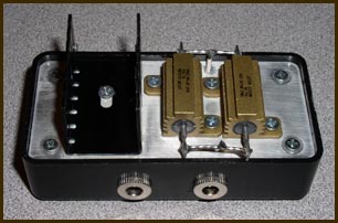
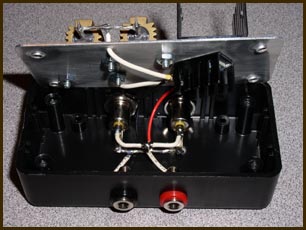
Notice the dual input jacks for different power supply types, and the banana jacks connected to them for monitoring the loaded power supply. Because the regulator and the resistors are separately heat-sunk, it stays cooler than my earlier effort, which put everything onto a single heat sink.
Parts
The enclosure is a Radio Shack project box. I don’t have the part number, but you'll know it when you see it. There isn’t exactly a big selection to choose from. You could also use a generic Bud or Hammond cast aluminum box, for better heat dissipation.
The resistor value sets the current: R = 1.25 / I, approximately, where I is the desired current. (See the LM317 datasheet for the exact equation.) In the picture above, you can see that I used two 10 Ω 25 W resistors in parallel, to give 250 mA. You probably don’t have to use such high-wattage resistors as the ones pictured above, since there’s only 1.25 V across them. I just had these ones on hand, and they do lend the project a certain geek esthetic. :)
For inputs, I used both 2.1mm and 2.5mm barrel jacks, since I have power supplies and battery packs that have both connectors on hand. For test outputs, I used a pair of banana jacks. You could use a single BNC to save space, if not cost. You might want to think this one through, because I ended up needing some BNC to banana adapters for some of my tests, so it might have been cheaper in the long run to go with BNC.
The extra heat sink on the inside is just there because the room was there. You can forego it if space doesn’t allow it. The more heat sinking you can add, the longer it’s likely to last. If, like me, you're dropping up to 30V across this unit and have it configured for a 250 mA load, that’s 7.5 W of heat you’ve got to get rid of.
Assembly
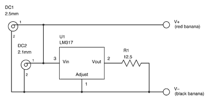
Here’s the schematic for a 100 mA version of the smarty load:

|
The DC input jacks are shown with tip-positive connections. If you happen to have one of the less common supplies with tip-negative connections, be careful that you wire the jack correctly.
Between the schematic and the pictures above, it should be pretty obvious how it all goes together. The only thing I want to mention is that you have to be pretty careful how you arrange the parts on the inside so the jacks don’t run into the regulator. I had to mount my regulator on a diagonal to avoid problems here.