Op-Amp Based Linear Regulators
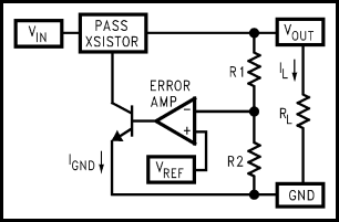
Experienced audio DIYers are familiar with monolithic linear regulators like the 78xx series and the LM317. Here’s a simplified block diagram of a standard linear regulator, from National Semiconductor’s Application Note 1148:
|
Let’s see... We have an op-amp, a couple of transistors, a voltage reference, and a few resistors. Can we build a linear regulator from these individual components? Yes, we can!
Why DIY a Regulator?
Before monolithic IC regulators became popular, people made linear regulators from discrete components and maybe a general-purpose IC or two. I’ll call them DIY regulators, lacking a better term.
Like the μA741 IC op-amp did to small discrete amplifiers in the late 1960’s, the invention of the 3-terminal fixed IC regulator a few years later started pushing out DIY regulators and fully discrete regulators. These IC regulators are easy to apply, take up little board space, and have quite good performance. The secondary effects of these facts are that 3-terminal regulators like the LM317 are made by several manufacturers, and you can get them for as little as about 50 cents in single quantities. And if you want to spend a little bit of money to get even better performance, there are many improved regulators on the market. So why would one want to return to the days where people made their own linear regulators from generic parts?
The main problem with the improved IC linear regulators on the market is that they have nonstandard pinouts and they can be fairly expensive. Consider the Linear Technology LT1581 high-current high-speed LDO regulator: it’s a 7-pin TO-220 type package and it costs about $13 for single units. For $13, you can buy a pretty good collection of parts. If you can afford the board space the DIY approach takes up, you can often equal or better the performance of monolithic IC regulators.
This article follows the history of a popular series of DIY linear regulators. Starting from initial concepts basically identical to the archetype block diagram above, this particular thread through history will wind up in a very sophisticated design. Because this final design developed piecemeal over the course of two decades, that’s how I’ll show it. I think showing the steps this series of designs went through aids understanding of the final design.
We will follow the thread through the pages of the journal The Audio Amateur, the forerunner of audioXpress. audioXpress offers a complete catalog of back issues going back to 1970, so that’s how I followed the history. (Most of the back issues are still available in printed form; a few years in the 1970s are sold out now and are only available on their 1970’s reprint CD.) My purpose here is not to duplicate this material, but to summarize it and serve as a guide to it. If you want the full details of these designs, I recommend that you get the issues I reference. Many of these articles have a lot of information in them that I am glossing over here.
How Does a Series Linear Regulator Work?
The archetype block diagram above is called a series linear regulator, because the pass transistor is in series between the input and output. This type of regulator is based on a simple idea: you can control the voltage at the output leg of the transistor by manipulating the voltage at the base. Let’s study the archetype design above.
Connected to one input of the op-amp (called the error amp) is the voltage reference, VREF. You can make voltage references in many different ways, so the technology used isn’t important at this point. A good reference puts out a fixed voltage under varying conditions, and you can get versions that put out any of several standard voltages.
Connected to the other input of the error amp is the midpoint of a voltage divider. We’ll come back to this later.
An op-amp tries to make its two input voltages equal by adjusting its output voltage. In the diagram, the output of the error amp is connected to the base of an NPN transistor: when the error amp drives current into this transistor’s base, it allows current to flow from collector to emitter, and that transistor in turn pulls current from the base of the pass transistor. This arrangement lets an op-amp capable of driving a few tens of milliamps control an amp or so of current across the pass transistor.
Now comes the neat bit. Let’s say you have a 5V reference and the voltage divider is set up to divide the voltage from VOUT to GND by 4. Since the op-amp tries to make its two inputs equal and one input (the voltage reference) stays constant, it will adjust its output voltage until 5V appears at the midpoint of the divider. Since it’s a divide-by-4 voltage divider, VOUT goes to 20V and it stays there because it’s a real-time system, constantly adjusting to changing conditions.
Voilá, you have a series linear regulator.
(If you want to read more about the operation of linear regulators, I recommend reading the AN-1148 app note I reference above.)
Now, this simple design isn’t perfect. The error amp can only slew so fast, the voltage reference will have some error, the output of the regulator has an effective impedance resulting in current-modulated voltage drops, and all of the components in question will drift to some extent as the temperature changes. Furthermore, all of the components in the regulator generate some noise, and this gets worse as temperature rises.
Sophistication Begins: The Sulzer Regulator
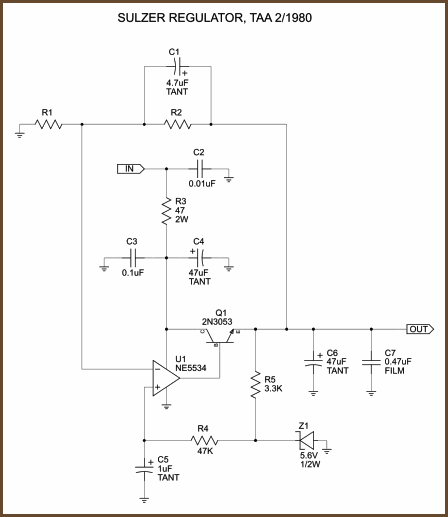
In the 2/1980 issue of The Audio Amateur Mike Sulzer published this regulator design:
|
There are several subtle improvements in this design relative to the archetype:
- It uses the fast, low-noise NE5534 as the error amp.
- The unregulated supply voltage ripple is largely filtered by a RC
low-pass filter with a low corner frequency (R3 and C3+C4), and the
zener noise is mitigated by another filter, R4 and C5. These filters
are a step beyond the bypass caps you find used on monolithic linear
regulators, because they’re so tightly woven into this design.
- The large C1 cap rolls off the gain of the regulator starting at a low frequency so that high frequency noise isn’t amplified by the error amp.
Output voltage is VREF × (R2/R1 + 1).
The NE5534 was the hot new chip back in 1980, priced at about $13 in 2008 money. Now the NE5534 is generic, and you can can get them for under $1. The cost of the op-amp pretty much exchanges evenly with the cost of an LM317. The parts above and beyond what you’d add to an LM317 circuit (say, 3 caps and 2 resistors) should only cost a few dollars more, and the performance should be better than you get with an LM317. I’m reliably informed that the error amp within an LM317 is closest in performance to a 741; as the error amp’s performance goes, so goes the regulator’s performance. Some look back on the NE5534 with disdain these days, but it’s still miles ahead of the 741.
There’s a lot of good information in the article about how Sulzer designed and tested his regulator, so it’s worthwhile to dig this one up if you plan on making Sulzer regulators.
Sulzer Variations
In the 1/1981 issue of The Audio Amateur, Sulzer published a follow-up article. This article feels more like a collection of random ideas thrown out for people to try, rather than another strong design like the first article. Since there are later variants that perform better and are no more complex, I won’t show a schematic for the ’81 circuit.
The following ideas first appeared in the 1981 article:
- using an LM317 as a pre-regulator
- replacing the zener with a precision voltage reference
- connecting the pass transistor’s collector directly to the unregulated supply
- adding another, bigger transistor on the output in Darlington configuration to get more output current
The most notable of these advances is the pre-regulator. It keeps the voltage drop across the pass transistor more nearly constant, improving its performance. It also removes the need for the low-pass filter on the V+ pin of the error amp, which saves on parts and probably improves the op-amp’s performance since it reduces its supply impedance.
In the 1980 article, Sulzer credits Jim Breakall (among others) with helping with the design of the regulator. In the 1/1983 issue of The Audio Amateur Breakall and others published an article with an extensive series of tests of what is basically Sulzer ’81. They focused on output impedance, and they compared the new DIY design with the LM317 and LM340. They also tested a few different op-amps in the regulator. As one might guess, the Sulzer regulator with a 741 in it performed about the same as an LM317, but with a good op-amp the Sulzer regulator greatly surpassed the LM317. They did show a small amount of improvement from adding the pre-regulator, but not as much as you might think. This article is worth digging up for the test results and methods.
In the 1/1987 issue of The Audio Amateur, Jan Didden chimes in with some variations on the Sulzer regulator. He uses a 7818 as a pre-regulator and a 7805 as a reference, and he uses a better pass transistor than the generic one Sulzer used. It’s an interesting circuit, but I don’t think it’s worth showing here.
Sulzer-Borbely Regulator
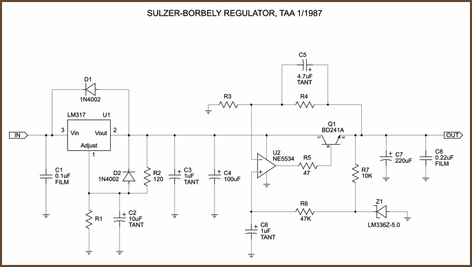
Also in the 1/1987 issue, prolific designer Erno Borbely published a moving coil preamp with a Sulzer type regulated power supply. Borbely didn’t go into any details about his variations, probably because it really isn’t a major improvement. The Borbely variant is mostly a thoughtful pick-and-choose exercise from the ideas that went before. It’s a solid design worth repeating:
|
The most notable improvement over the ideas in the Sulzer and Breakall articles is that the preregulator is more thoughtfully implemented.
The only quibble I have with the Borbely design is the choice of the LM336 band-gap reference. The main thing about band-gaps is that they can be made with much lower voltage drops than zeners, but they are noisier than a buried zener type reference. Since we don’t need the low voltage feature for high-quality audio, I think it’s more sensible to go with an LM329 buried zener here. Nevertheless, a band-gap reference is still an improvement over a standard zener both in terms of noise and stability. It’s just that a buried zener is even better, if you can afford the higher voltage drop.
Jung Super Regulator
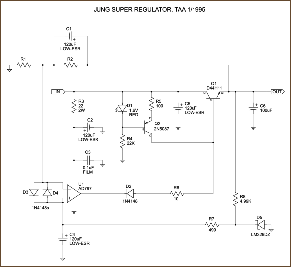
Finally we come to the Jung regulator. In the first two issues of TAA in 1995, Jung describes his circuit and gives some very detailed test results of it vs. several other linear regulator types. In issue 3, Jan Didden gives a PCB layout for the circuit and gives some advice for applying the regulator circuit. And in issue 4, Gary Galo does some subjective tests on the regulator dropped in as mods to real circuits, with side-bars written by Jung and Didden. If you only want to pick up a few back issues of all the ones I mention, pick up the first two in this series at minimum. The full set of four is very helpful.
|
The major differences in the Jung regulator relative to the original Sulzer design are: better pass transistor (D44H11), different drive scheme for pass transistor, no pre-regulator, better op-amp (AD797), op-amp protection, precision reference (LM329), and remote sensing.
The error amp in the Sulzer regulator effects voltage regulation in a standard way: it varies its output current which changes the voltage drop across the pass transistor. The Jung regulator uses a much different control mechanism. In the Jung regulator, a constant current source (Q2 and assocated parts) pushes current to the base of the transistor, and the error amp sinks as much of this away as is required to maintain the desired output voltage. (The diode inline with the op-amp’s output is why it can only sink current.) There are two big adavantages to this configuration. First, the CCS indirectly limits the maximum output current of the regulator to a reasonable value. A short across the output of a stock Sulzer regulator would probably destroy the pass transistor. Second, it pushes the error amp’s output stage deep into class A, eliminating crossover distortion in normal operation.
There is a low-pass filter on the op-amp’s V+ pin as in the original Sulzer design (R3, C2), but Jung says this is optional. One gets the impression that he’d rather just depend on the power supply ripple rejection behavior of the op-amp. There’s some worry that the resistor in this filter could have load-modulated voltage drops across it, thus possibly increasing the ripple at the supply pins. In the fourth article in the series, Gary Galo says he heard a difference between a version with the filter and without, and says he prefers the version with the filter.
Notice that the pass transistor’s collector connects directly to the unregulated supply input, not after the low-pass filter like in the original Sulzer circuit. This keeps the high-current path low in impedance and lowers the influence of the output current on the op-amp’s power rails.
The diodes on the error amp’s inputs protect it from overvoltages. Some op-amps have diodes across the inputs like this already, but even a small discrete diode can pass far more current than the on-chip diodes.
There are a few layout considerations pointed out in this series. They aren’t part of the circuit design per se, but they are part of the intended implementation. (You could do both of these to the Sulzer variants as well.) First, R2 and R8 do not connect directly to the output of the pass transistor as drawn. Instead, just connect them together and put a wire pad between them. Second, I used two different ground symbols in the schematic; each one is a separate star ground. The two wires from the pass transistor’s output and the R2/R8 junction go to the positive side of the load. This allows the error sense circuit to see all errors that happen between the output of the regulator proper and the load. A separate wire from each star ground centerpoint goes to the negative side of the load, so the noise bypassed to ground from the control and sense circuits only mix at the load/sense point, so the error amp can control these errors as well.
If you do run separate wires from the control and sense grounds to the load, you should also connect the ground of the unregulated section of the power supply to the negative side of the load to avoid a ground loop. Also, beware that there is a risk to remote sensing: it greatly increases the size of the error amp’s feedback loop, and it adds significant inductance and probably also capacitance from the long wires into this loop. If you add remote sensing, you must test the power supply for oscillations, especially if you use the fast op-amps that Jung recommends. The fourth article in the series has info on troubleshooting oscillations.
Jung 2000 Regulator
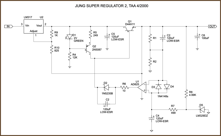
In the 4/2000 issue of Audio Electronics (successor to TAA), Walt Jung published a new version of his regulator with several improvements over the 1995 circuit:
|
I’ve used the same component names as far as possible to aid comparison to the 1995 circuit. I reuse the C2 designation because it’s actually the same capacitor on the modified Didden boards, though it has a new role in this circuit. In all other cases, new components have new names.
The first thing you notice is the LM317 pre-regulator, but I’ll talk about that later. Pretend for the moment that the input comes from just before D1.
Far more important is the change to the error amp’s power connection. Notice that V+ comes from the output of the power supply. The error amp runs from the regulator’s clean output power instead of lightly-filtered unregulated power. Obviously R3 and C2 are no longer needed with this configuration. C3 also had to be removed because you can’t use a film bypass cap on the error amp’s V+ supply any more because the amp becomes unstable if the output cap’s impedance is too low.
The diode on the error amp’s output is now a 6.8V zener. This helps the regulator start up more reliably. It may be needed in difficult situations in the original Jung circuit, but Jung says it’s absolutely essential in this new circuit. If you were to use a regular diode, the the error amp’s output is likely to lock up near the negative rail on startup.
The circuit now uses the AD825. Jung says the AD797 had problems in environments with strong RFI, since its sensitive inputs would rectify the interference and make the output of the error amp unstable. FET input chips are less sensitive to this problem. Emitter-degenerated bipolar input chips are also said to be workable; Jung recommends the AD817. You still want a fairly fast chip for this purpose, and a strong output stage helps.
The current source’s default value has been lowered. The D44H11’s minimum hFE is 60, so the minimum current from this configuration is about 330mA. If you mirror this circuit for a negative regulator, the complementary D45H11’s minimum hFE is 40, so the minimum current would be more like 225mA. You don’t want to increase the circuit’s output level needlessly because that puts an unnecessary load on the output stage of the error amp.
The LED and its series resistor have been changed to match recommendations by Gary Galo in part 4 of the 1995 series. Galo said these lower the dropout voltage. Jung does mention using the 2N2907 instead of the 2N5087, but he doesn’t mention dropout, though Galo said this helped as well.
And now for that LM317 pre-regulator. Jung’s implementation is infinitely more clever than the pre-regulators used by Sulzer and Borbely. Because the LM317 is a floating design, Jung is able to wrap the regulator around the pass transistor so that the output of the preregulator always stays a fixed amount above the output of the pass transistor. The resistor values shown give a 2.3V drop across the preregulator, which should be high enough that you can pull 1.5 A from it without hitting dropout. The preregulator reduces the amount of ripple the error amp has to remove, it reduces small errors through the current source, and it takes some of the power dissipation load off the pass transistor. The only downside to the preregulator is that the dropout voltage of the combined regulator rises to around 5 V.
The article describes the changes as mods to the Didden circuit boards, so I suspect the boards distributed by audioXpress are still the original design.
Schematics
The schematics above are available as a PDF (36 KB) which will be easier to read than the graphics above.
Final Comments
Walt Jung has copies of many of the articles he’s written on his web site. He’s collected the ones relevant to this article’s topic here. (Note in particular that he published two intermediate circuits between the 1995 series and the 2000 culmination.) As you can see, Mr Jung has been thinking about this since at least 1974, in which he gives essentially the same circuit as the archetype at the top of this article. Nevertheless, I think the 1980 Sulzer circuit really kicked off a new direction in DIY regulator design by concerning itself with cleaning up the error amplifier’s input power.
Jeffrey Jenkins offered some helpful technical help with this article, which has been incorporated since the original publication.