How to Wire Panel Components
So you’ve got a headphone amplifier board assembled and working on the bench, the case has all the holes drilled in it and you’ve mounted the components... Now what? This article takes you through the steps you need to hook a typical headphone amp up to the panel components.
Switches
There are so many types of switches out there that I cannot hope to cover everything. However, some basic concepts will help you to figure out the pinout on your switch.
Switches are specified in terms of “poles” and “throws.”
Poles are the number of common points within the switch. In a toggle or rocker switch, the pole lugs are usually along the center line of the switch. In a rotary switch, there are usually two rings of lugs and the pole lugs make up the center ring. For anything more complicated, you will probably have to get the switch’s datasheet to figure out its circuit paths.
Throws are the number of unique paths through the switch per pole. It’s kind of a confusing term because “throws” implies that it’s talking about the number of positions of the switch actuator. (Think of the term “throw the switch.”) The number of actuator positions sometimes does equal the number of throws, but if there are any “off” positions, they don’t count as a throw, since there is no path from the pole lug to one of the other lugs in that switch position.
Take a SPDT toggle switch: single pole, double throw. It has three lugs: the center one is the pole and the other two are for the throws. In this type of switch, the pole lug is connected to one of the other two lugs depending on the position of the actuator. Now make it an SPST switch: it’s the same thing but with one throw lug removed, making for a basic on/off switch. DPDT: same as SPDT but with everything doubled. You get the idea.
I/O Jacks
I could put information about specific jacks here, but instead it’s better to learn how to sound out the pinout of a jack yourself. That way you’re not limited to using just one kind of jack.
The basic procedure is to hook some kind of patch cable up to the jack and then use your ohmmeter to find out what part of the cable goes to which pin or lug on the jack. Even a cheap $9 multimeter will work for this. If you don’t have even that, you’re going to have to look up the schematic diagram for the connector and figure out how to read it. This ohmmeter technique is so much simpler, though, that I’ve never bothered to learn how to read the more complicated jack symbols. It’s just not worth the bother.
For 1/8" and 1/4" plugs, the tip is the left channel, the next part down the plug (the “ring”) is the right channel, and the long final part (the “sleeve”) is the ground connection. (You will sometimes find these called TRS or tip-ring-sleeve plugs.)
RCA jacks are trivial: the plug part carries the signal, and the cylindrical part is the ground connection. In all cases, the ground lug needs to be connected to ground in the amp circuit.
Potentiometers
The potentiometer is trickier. They have three connections per channel. Think of a pot as a pair of resistors configured as a voltage divider, because that’s what it is! (Play the video at right for a detailed explanation.)
Two of these per-channel connections are fixed, and go to the input jack and to ground. Which one is which depends on whether you want volume to increase when turning the knob clockwise or counterclockwise. The pot doesn’t care, it’ll work either way.
The third per-channel connection is typically positioned between the other two on the pot body, but not always. It is the variable output of the pot, and is called the “wiper.” It goes to the input of the next stage; in most of the amps on this site, that’s the input capacitor. So, as you turn the knob, the input signal goes into the pot, gets divided down depending on the position of the wiper, and leaves the wiper lug to go into the rest of the amp.
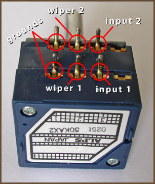
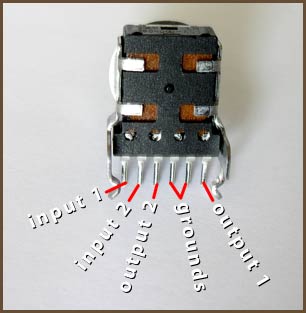
Here are the pinouts for the pots I talk about most often on this site:
|
|
| ALPS RK27 (and many others) | Panasonic EVJ-C20 |
The left pinout is common to a great many pots, from different manufacturers. Just off the top of my head, I’ve seen this arrangement on the ALPS RK097, the Bourns 51 series, some Nobels, some Clarostats... If you ever see a pot with three pins in a row, chances are good it shares this same pinout.
If your pot uses something that looks very different from the left picture, you may have to use a multimeter to figure it out. You should know the total resistance number for the pot. Adjust the pot so it’s about halfway through its range. Then, measure between pairs of pins until you find two that give you about this rated resistance. (Most pots have fairly poor accuracy, so if the pot is nominally 50 kΩ, you might actually measure 51 kΩ or 48 kΩ.) These are the fixed connections for one channel on that pot. Then measure from either of the fixed pins to the remaining pins until you get a reading. That will be the wiper, and if it’s a true log taper pot, the resistance should be about 15% or 85% of the total resistance rating, depending on which end you’re measuring from. If it’s a linear taper pot, it will be about 50% of the reading from end-to-end. Other tapers give different values at the halfway point. One pot I have here with a specialty “audio” taper gives a 35/65% split, for instance. Check this measurement by measuring from the wiper to the third lug to ensure that both measurements add up to the total resistance you measured earlier.
DC Power Jacks
You can skip this section if you’re using battery power exclusively.
Simple Single-Voltage DC Power Jacks
Most single-voltage DC power supplies use a barrel connector of some sort. The inner part can be positive or negative. There is no standard, so you’ll have to use your voltmeter to find out which it is. You can then use your ohmmeter to find out which lugs go to which parts of the plug. This will tell you where to run the V+ and V- wires from the amp board. For a simple 2-lug DC power jack, that’s all you need to know to hook it up.
Closed-Circuit DC Power Jacks
You can also get a “closed circuit” type of DC power jack, which has three solder lugs. This type of jack is used for hooking two different power sources to your circuit, such as batteries and wall power. Two of the jack’s lugs are permanently connected to the pin and outside barrel parts of the jack. The third is connected to the barrel while nothing is plugged into the jack; in other words, you have a normally-closed circuit to the barrel lug, which is how this type of jack got its name. When you plug something into the jack, this circuit opens.
|
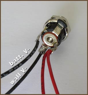
So, how is this setup useful? Suppose you have a tip-positive power supply, and you hook it and your battery up like in the picture above. When the DC power is not plugged in, the two black wires are connected together through the normally-closed circuit. Since the V+ wires are tied together at the jack as well, the battery powers your circuit. When the wall power supply’s barrel plug is plugged in, the normally-closed circuit between the black wires opens, so only the one labelled “wall V-” is connected to the barrel of the plug. Since the battery circuit is broken, only the wall supply powers the circuit. This is good, because otherwise the wall supply would try to “charge” the batteries, thereby causing them to fail.
Dual-Voltage DC Power Jacks
A third possibility is if you’re using a dual-voltage power supply. For example ±12V instead of 24V. This type of supply has at least three pins. In practice, it’s common to see these supplies using some sort of DIN connector, particularly DIN-5, with two of the pins either unused, supplying a third voltage, or doing some special function. All of the amp circuits described on this site have virtual ground circuits of some sort built into them to split a single supply voltage into two opposite voltages. Going with a true dual supply does have some advantages, particularly in circuits that use the simpler types of virtual ground divider. (e.g. CMoy, META42, MINT...) To hook this up, you would remove the voltage divider in the power supply (and the buffer in front of it, if any) and hook the ground lug from the power supply to the virtual ground point. (Only now, it isn’t “virtual” ground any more, it’s real ground.) V+ and V- from the power supply still go to V+ and V- on the amp board.
Regardless of which way you go, keep the grounding issues in mind.
AC Power Jacks
Audio circuits run from low-voltage DC power, but the power company gives you relatively high-voltage AC. Since one can buy ready-made AC-DC power supplies that will work with jacks like I describe above, this is the simplest and safest way to go.
If you’re willing to risk playing with AC line voltages, though, you can build your own power supply. In DIY projects, it’s most common to use a standard IEC-320 power receptacle. This is the same type of receptacle used on your computer’s power supply, and probably a half dozen other things in your home. Because this is a popular worldwide standard, the power cords suited to each country’s power system are readily available.
There are three lugs on an IEC jack: AC line, AC neutral, and earth ground. You must hook up at least the first two. The lugs are always labeled in my experience, usually L, N and G. The third lug is sometimes not hooked up, either because the country’s power system doesn’t use earth ground, or to avoid ground loop problems. Personally, I always hook it up whenever I’m using a metal chassis, and deal with any ground loop problems directly because of the safety factor the earth ground provides. The earth ground lug should be connected to the chassis, and possibly also to other parts of the power circuit; this article isn’t the place to talk about all of the possibilities.
If you do connect earth ground to the case, the grounding issues discussed in the next section apply here. You often don’t want to tie signal ground to earth ground, and you almost never want to tie V- to earth ground. There is no single scheme that will work with all circuits, so some informed thought will have to go into deciding how to hook up the remaining panel components.
I have some AC-DC power supply circuits you can apply this information to here.
Grounding Issues
You have to pay attention to grounding issues with your jacks if you use a metal enclosure. If any of your panel components have metal bodies, chances are good that one of the solder lugs is tied to this metal shell, and this will tie that signal to the enclosure when you tighten the mounting nut. If you have more than one such signal tied to the enclosure in this way, you have a problem.
A common conflict occurs when you add a metal-bodied DC power jack to a metal case. If the power plug is tip-positive, this ties the chassis to V-. Let’s say you are also using metal-bodied RCA input jacks: this will be a conflict if both are tied to the case, since the RCAs will tie signal ground to the case, and this is usually a much different voltage than V-. This is particularly a problem with circuits using virtual ground, as most of the circuits on this site do: virtual ground is supposed to be halfway between V+ and V-, so you can’t go and tie virtual ground to V- through the case!
The solution to this is to isolate all but one type of panel component. It’s usually best to tie the case to some sort of ground, so you could choose to tie the case to virtual ground through the input jacks. Then, you’d need to either get isolating washers for your metal-bodied DC input jack, or find an isolated (i.e. plastic-bodied) DC input jack. You could instead tie the case to V- through the DC input jack and isolate the rest of the panel components. This will often work okay, but it’s less desirable because V- is usually a floating voltage in audio circuits, so it makes your amp a little more susceptible to interference.