Step-by-Step Assembly Guide
If you're new to building amps, here's a step-by-step guide to assembling a META42 amplifier. If you're an old hand, you probably won't find much enlightenment here; you can skip to the next section.
The purpose of this tutorial is only to show you the steps for assembling the amplifier. It assumes that you know basics like how to solder, how to read a schematic, and how to wire a toggle switch. As a barometer, if you don't know how to hook two 9V batteries up to get 18V, you're over your head and should do some reading elsewhere before starting this project. You should consider finding an electronics tutorial online, or getting a book. You may find my Getting Started in Audio DIY and How to Wire Panel Components articles helpful. You might also consider starting with a CMoy amp before going on to the META42, for educational value.
1. Add the resistors
|
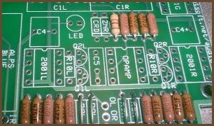
As a general rule, you should install the shortest components first, and on the META42 board that's the resistors. If you're going to socket the resistors, you can still do this step first.
Notice that I've used high-spec Vishay-Dale RN55 series resistors for everything but RLED. RLED can be any old junk resistor, but all the other resistors are in or associated with the signal path, so they benefit from higher-quality parts.
The picture doesn't show it, but if you are going to use the LED cutoff feature of the board (ZNR/CRD) you can also populate those positions now.
2. Add the TO-92 parts
|
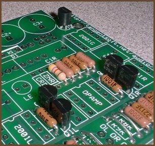
This is the TLE2426 and the cascode JFETs. Both of these are optional on the META42.
The META42 board is designed with single-voltage supplies in mind, and in this case, you need the TLE2426. However, you can instead use a true dual-voltage power supply, allowing you to leave out the TLE2426 and its buffer (2001G). If you do that, V+ and V- from the power supply go to the + and - pads on the board, and GND from the power supply goes to any point on the trace running around the edge of the board.
As for the cascode, if you want to try it but want to hear what the amp sounds like without the cascode, you can pass over this step for now. You can always add the cascode later. However, you may find it easier to add R10 up front, since it's mildly tricky to add the resistor later if you add sockets for the buffer and op-amp chips, since the sockets are taller than the resistors. It's not hard to add the JFETs between sockets.
3. Add the diodes
|
|
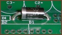
To protect your META42 from reversed supply voltages, you can add either D1 or D2. D1 is better for battery supplies (relatively low voltage, high current capability), and D2 is better for wall supplies (possibly high voltage, current inherently limited).
D1 is straightforward: it goes into the holes you expect it to.
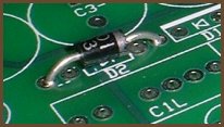
D2 is trickier: you need to jump across the frontward switch pads to the D1 pads for D2 to do its job. Furthermore, you can't wire the power switch to the PCB if you use D2; you must wire the power switch inline with one of the leads coming from the power supply. (Or inline with both leads if you're using a dual supply.) Since D2 is normally used with wall power supplies and the power switch and DC input jack are generally placed near each other on the back panel, this is not a hardship at all.
In either case, notice the direction of the stripe on the diode body.
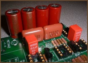
4. Add the capacitors and sockets
|
Now that all of the small components are placed, you can start placing the large ones. Notice that the electrolytic capacitors (C2/C3) are polarized: the long lead must go into the hole with the square pad. The remaining caps (C1, C4 and C5) are not polarized; they can be placed in the holes in any orientation.
Notice that C5 is not populated. I have personally never had to populate this position. You should only try something here if you're getting oscillations that you can't fix some other way.
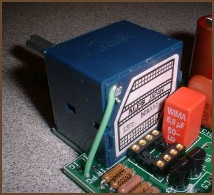
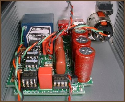
5. Add the pot
|
Now add the final large component: the volume control. You may need to run a wire from the pot's case to the PG pad as shown in the picture above. If you get humming when you touch the pot's shaft, try adding the ground strap to see if it goes away. If you get some other kind of noise, especially if it happens when you're not touching the amp, look elsewhere before grounding your pot. If the pot's shaft is plastic, the pot's case probably doesn't need to be grounded. (The Panasonic EVJ pot is an example of this.)
If you're using a metal case and a wall power supply, you have a potential confict. If your DC input jack is uninsulated, that means V- gets tied to the case. Now, you may be able to get away with that, but only as long as the pot (via PG) and the I/O jacks are all insulated from the case. Otherwise, you end up tying V- to virtual ground via the case. If your amp doesn't fail outright, it will at least misbehave badly. Instead, it's better to insulate the power input jack from the case somehow; get an inherently insulated jack if you can. Then you can tie virtual ground to the case via the pot and I/O jacks without problems.
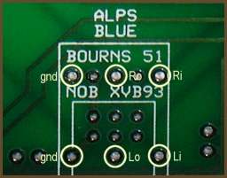
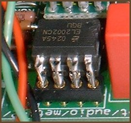
If you have a pot that doesn't fit one of the footprints provided on the board, you can run wires from it to the board. I recommend you use the ALPS Blue pins, as they are the biggest and widest spaced. These pins used to be labeled on the v1 board, but the labels had to be removed for space reasons. Here's what the labels would have been if we could have fit them on the board nicely:
|
The 'i' pads go to the input side (i.e. the source), and the 'o' pads are the pot's output (i.e. the wiper). The 'gnd' pads, obviously, are for the ground connection.
6. Test the power supply
Run wires from your power supply to the + and - pads on the board.
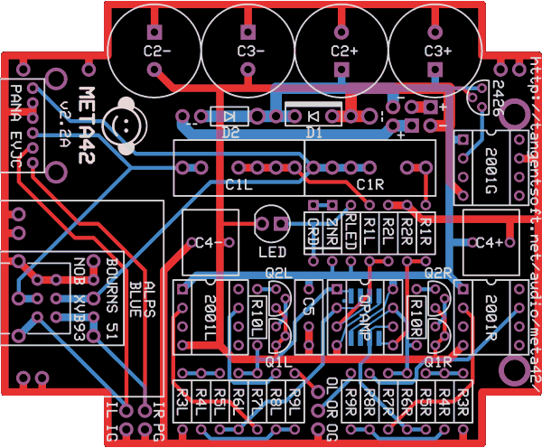
v2.1B NOTE: Due to a layout accident, these pads are not labelled on this board run. Use the board layout image to find these pads on your board.
v2.2+ NOTE: In this and future versions, there are two sets of + and - pads, arranged to allow two power sources in series. Typically, this will be something like two 9V batteries or 2 AA cell holders in series. If you've got a simple power supply, use the lower + and - pads. If you have two batteries you want to hook up in series, use the lower pads for + from one battery and - from the other, and put the remaining two wires in the upper pads. This hooks the two power sources together in series through the upper pads. Study the board layout image to see how this works.
Next, run wires to the power switch pads (- -) unless you're using D2. (The dashes are symbolic of two wires, which the switch connects.) There are two sets of power switch pads; use whichever is most convenient. Just measure and cut the wires and solder them to the board; don't bother to solder them to the panel components yet. Strip and tin the free ends.
You may also want to add the LED at this stage. The square pad is for the LED's positive lead (anode), which is usually the long one. Check your LED's datasheet to be sure, though!
Next, install just a single buffer in 2001G, hook a power supply to the supply wires, and jumper the power switch wires together. The LED should light up, and if not, find out why. If the LED lights, check the voltages at all four chips' supply pins relative to virtual ground. If you don't get the voltages you expect, find out why before proceding. (If you leave out 2001G, you won't get the voltages you expect. "Why" is left as an exercise to the reader.)
If you've installed the current sources already, you should also check that the output pins on the op-amp are equal to V-. You may also check that all other pins are at 0V or very near to it.
When you're satisfied that the chips are receiving the proper voltages, turn off power.
7. Assemble your buffer stacks
|
If you're going to stack the buffers, now is a good time to solder up your stacks. I recommend bending the leads of one buffer per socket so that it goes into the socket easily. Then put one of these formed buffers at the bottom of each stack so the whole stack can be inserted into the board easily.
The buffers all go in the same orientation. (They are in parallel.)
8. Do the casework and wiring
|
Now that the amp board is assembled and the power supply section is known to be working, set it aside and do the casework.
If you haven't yet read my How to Wire Panel Components article, go read that now.
Install all the components in the panels, and hook them to the amp board with wires:
Power input: There are two + pads and two - pads on the board. The pair farthest from the C2/C3 bank goes to the amp's power rails; we'll call those the "primary" power pads. If you have a single power source, just hook it up to the primary power pads. The secondary pair is for hooking two batteries up in series. You run + from one battery and - from the other to the primary power pads and the other two wires to the secondary set. The secondary pads are tied to each other on the board, so this ties + of one battery to - of the other, so they are now in series.
Power switch: There are two pairs of pads marked - -. When you tie one of these sets together, power can flow. Just use the set closest to where your power switch is mounted in the case. If you're using D2, the power switch pads on the board aren't useful. You put the power switch inline with one of the power leads going to the board instead.
LED: You can either stick the LED itself on the board (good if you're putting the amp in a clear case) or run wires from the pads to where the LED mounts on the case. The LED's polarity matters; be sure you match the LED's anode to the square pad. The long leg of the LED is usually the anode, but check your datasheet to be sure.
IL, IR, IG: Signal input. Left, right, and ground, respectively.
OL, OR, OG: Signal output.
If you have multiple sets of inputs or outputs, wire only one set for the moment.
9. Test the amp
Turn the amp's power on and do a quick re-check of the voltages at the chip supply pins. The LED should be lit. Turn the amp off and wait until the LED goes completely out. (It will probably take a few seconds.)
Install the remaining chips and turn your amp on. Let it sit for a few seconds and then touch the chips to see if any are getting warm. If they are, you've probably got a fault of some kind. If the chips are staying cool, turn your meter to the DC millivolts scale and measure from virtual ground to each output pin: you should be getting an absolute voltage of less than 20mV. If you're getting high DC offset levels, you have some debugging to do before you plug headphones into the amp.
Now that we're reasonably sure the amp is safe to plug headphones into, ensure that the volume knob is turned all the way down, plug the source into the amp, plug some cheap headphones into the amp, and start something playing. Leave the headphones on the table, and slowly turn up the volume. If the volume shoots up quickly and sounds crackly, you've got some kind of oscillation going on. (Aren't you glad the headphones aren't on your ears now?) Turn the volume down and find out what the problem is before continuing. If the volume changes level gradually as you turn the knob, put the headphones on and listen critically. Ramp the volume up and down gently. Then turn the knob back down and try the amp with your good headphones, repeating these tests.
10. Add extra features
Once everything's working correctly, wire up any secondary input and output jacks and re-test. Finally, add crossfeed, multiple input switching, or any other extra features you want. Re-test after you add each new feature.
When all tests are passing, close the amp up. You're done! Time to sit back and bask in the glow of a job well done. Grab a beverage and listen to some music.