The System
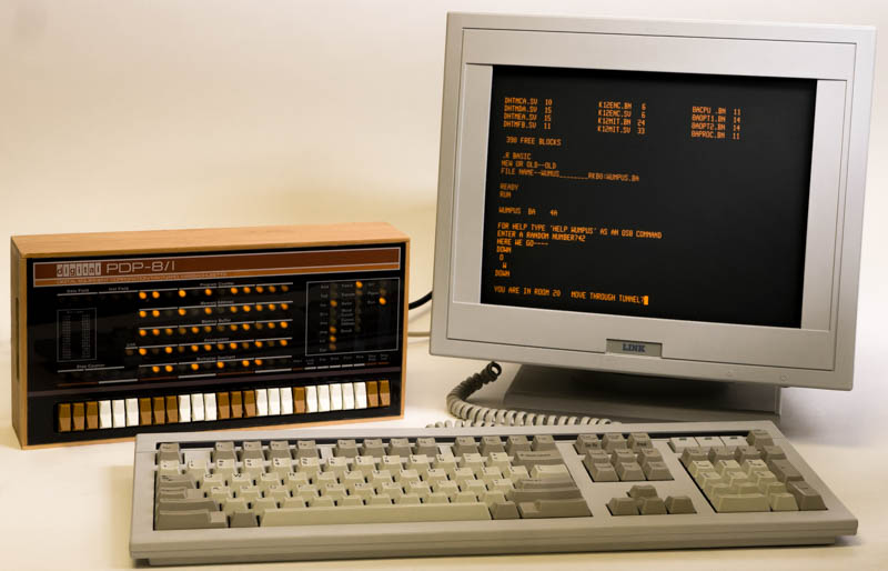
The terminal is a Link MC3+, which I selected on the following criteria:
Must have a DB-9 or DB-25 port. (Many terminals don't!)
Must support at least 115,200 bps, not because this project needs it, but because I want to be able to reuse the terminal on other projects, which often do go to that speed.
Must have an amber screen, as that is necessary for cosmetic matching to the PiDP-8/I.
Must ship from a reputable source in a reasonable time frame.
(i.e. No half-broken eBay junk, no "ships in 4-6 weeks" silliness...)
Must at least support VT52 or ANSI terminal codes, and VT220+ is a plus.
I'd have preferred to get an actual DEC VTwhatever, probably a VT320 or VT420, but I couldn't find one that met criteria 3 and 4.
Must weigh less than a mountain bike. I will not be buying a Teletype Model 33 ASR.
Yes, using a glass terminal from the 1990s (?) on a PDP-8/I from the late 1960s is cheating. I don't care.
Serial Port
As you can guess from the above, I definitely wanted to do the serial mod.
The standard PiDP-8/I instructions talk about using a generic TTL to USB cable if you want to use the serial port feature of this board. I wanted a DB-9 connector¹ instead, since I had in mind to use a glass terminal from the start.
I selected a DB-9 connector with attached port driver board which worked adequately. I say "adequately" because I could only get it to run reliably up to 19,200 bps, which is fine for my purposes here, since a real PDP-8 wasn't likely to run anything faster than 300 bps. It would have been nice to run it faster, but I think I prefer the esthetics of running it at 9,600 bps or slower. For a minicomputer of this era, you want to be able to see each character arrive on-screen discretely.
Here is the wiring at the DB-9/PCB connector end:
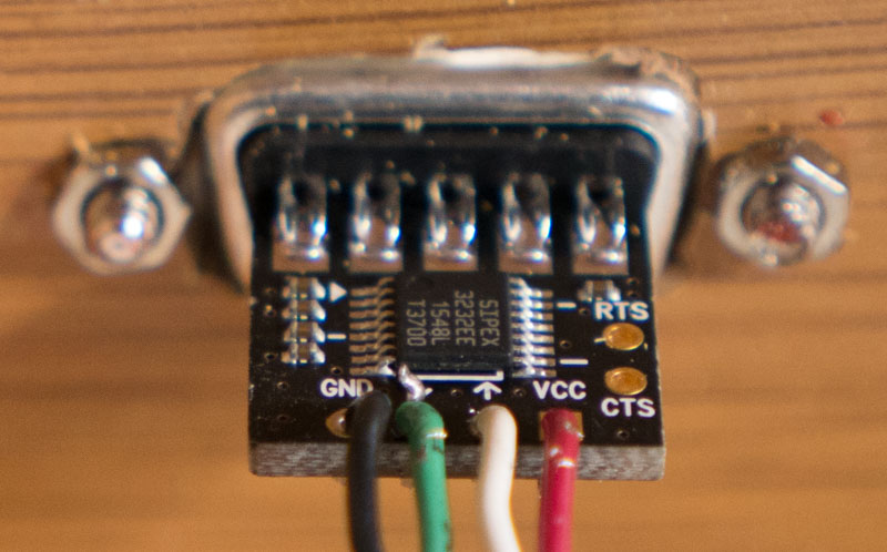
Notice the excess red thread locking compound. You want some hope that when someone screws the cable to the connector that it won't spin the screw studs out of the panel.
I purposely used the same color scheme as is standard for TTL to USB cables. I show this because the order of the two inner connections isn't obvious, but it is important. Although the 3232 IC does similar things for transmit and receive, it isn't symmetrical. Furthermore, the Raspberry Pi's UART output also isn't symmetrical. If you connect this backwards, you will get no comms, even if you swap the TxD and RxD pins in the external DB-9 cabling.
This works out for the best, since the most common type of DB-9F to DB-25M cable is in fact a null modem cable, which is exactly what is required in order to make the port and driver assembly talk to a terminal.
I chose to use a Molex KK connector on the PCB end:
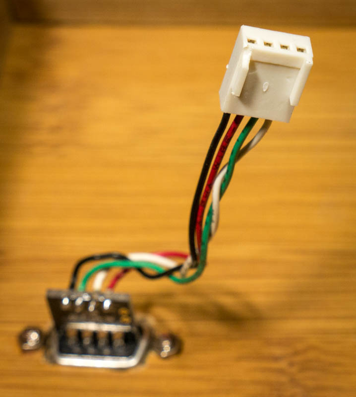
Again, note the wire ordering.
Footnote
- Technically it's a DE-9 connector, if you want to be pedantic. You will forgive me for using the terminology that the vast majority of the computing world has settled on even though it is not strictly correct.
The Front
Here is a close-up of the front end:
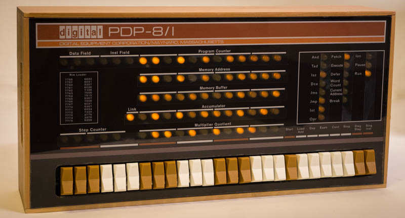
Notice that the panel is flush with the case edge. This is because I ignored the build advice to insert the switch flanges between the panel and the inner case lip. Instead, I bent the lower flanges down by about 45° so that they set the proper vertical position of the switches in the front panel opening. It was an iterative process: bend a little, fit the parts together, judge how much more to bend or un-bend the flanges until the vertical position was juuuust right.
There was a bit of a bump on one corner of the panel, which I partially sanded down, allowing the panel to press-fit tightly into the case without falling out, avoiding the need to run screws through that pretty front panel, risking a crack.
Fitting
Speaking of try-fitting, I found that the case was too deep for the supplied mounting blocks to push the switches sufficiently through the front panel. I ended up using some wood glue to attach some of the cardboard from the kit's shipping box to the back of the blocks. This turned out to give exactly the extra depth needed to push the electronic assembly toward the front panel sufficiently that the assembly doesn't rattle much when shaken prior to screwing the mounting blocks to the rear panel.
I also had to sand the long block down flush with the main PCB's right edge. The Molex KK connector I used for the serial port pushes the long block a bit over the right board edge, pretty much exactly the "2mm" that the official assembly guide claims you need in order to center everything properly, but at least with my enclosure, that caused the LEDs and switches to be noticeably shifted to the left relative to their proper centers. It's just as well that I had to do this, as the Molex connector hangs a bit off the left edge of the board, making for a rather tight fit of the assembly into the case, prior to taking this bit off the long block.
Attaching the Mounting Blocks
I found the official instructions for attaching the mounting blocks to the PiDP-8/I Front Panel PCB to be inadequate. I ran into a bunch of problems, with these resolutions:
As noted above, the official instructions' claim that you should have 2mm of the long block extending past the right edge of the PCB is wrong for my enclosure, at least. It ended up needing to be trimmed flush with the PCB's right edge. I did most of the work with a Dremel, followed by sanding to smooth the block end out.
The assembly pictures show a screwdriver running easily through the switch bracket holes to run one of the 9.5mm screws into the mounting block through the mounting holes in the PCB. As far as I can tell, there is no screwdriver that is small enough to fit through this hole while also properly engaging the screw. Therefore, I drilled out two of the bracket holes enough to allow a standard #0 Phillips screwdriver through the hole.
The pictures in the assembly guide show one of the small blocks placed right where the Raspberry Pi board mounts! I moved it inward, so that the block comes close to the Pi, aligned with the top edge. The other block is closer to the upper right corner, but not quite jammed into it. Instead of screws for these, I used a generous amount of 2-part epoxy, and clamped the two pieces together for several hours. I also sanded down the solder points to ensure a near-minimal gap between the block and PCB.
Why did I not just use screws to attach the small blocks to the PCB, as the official assembly guide recommends? I didn't want to risk breaking one of the LED traces, a distinct possibility with the blocks in the position I have them now.
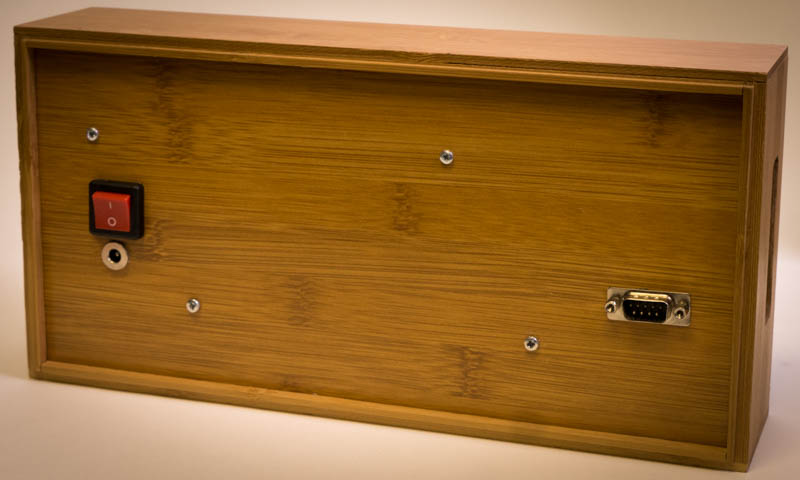
DC Input Jack
I absolutely hate micro-USB as power connector. It is barely adequate even as a data connector, IMHO. Therefore, I chose to install a 5.5/2.1mm DC barrel jack for power. I connected it to the expansion port, using a pair each of 5V and GND wires, so I could avoid unnecessary voltage drops without using too-large single wires.
I also added a power switch above the jack, though prior to doing that, I found that simply unplugging the barrel plug was reasonably convenient. If I didn't have the switch on hand, I doubt I would have bought one just for this.
Here's a schematic showing the connections:
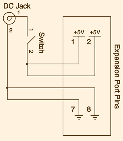
The End